
Which Eurocode 2 method does this example use?
The calculated crack width combines the maximum crack spacing with the difference between the mean reinforcement strain and the mean concrete strain. In the first-generation Eurocode 2 formulation, the calculation chain is:
This article uses EN 1992-1-1:2004, §7.3.4, with the example coefficients stated below. It does not substitute the newer edition’s rules into the older equations. Confirm the adopted edition, amendments, National Annex, relevant action combination and crack-width limit for the project.
The original worked example is deliberately simple: a singly reinforced rectangular section under short-term uniaxial bending, with no axial force or compression reinforcement. Concrete tension is ignored when calculating cracked-section equilibrium; tension stiffening enters the crack-width expression. Creep, shrinkage and imposed deformations are outside this example. A sustained or restrained project case needs those assumptions reconsidered.
Set up the section and service action
Use N, mm and MPa for the hand calculation. Convert the service moment from kN·m to N·mm before using it with the section dimensions.
| Input | Value |
|---|---|
| Section width b / depth h | 300 mm / 500 mm |
| Tension reinforcement | Four high-bond Ø20 bars in one layer; As = 1,256.637 mm² |
| Cover c to longitudinal bar surface | 40 mm; no enclosing link is included in this idealised geometry |
| Effective depth d | 450 mm; bar centres are 50 mm above the tension face |
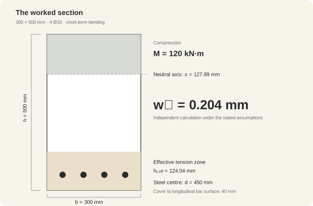
| Service action | M = 120 kN·m; N = 0; bending puts the bottom layer in tension |
| Concrete | C30/37; Ecm = 33,000 MPa; fct,eff = 2.9 MPa |
| Reinforcement modulus Es | 200,000 MPa |
| Example coefficients | kt = 0.6; k₁ = 0.8; k₂ = 0.5; k₃ = 3.4; k₄ = 0.425 |
The tensile strength is taken at the assumed concrete age for this example. Early-age cracking needs the appropriate age-dependent value. The geometry describes a section calculation, not a complete reinforcement detail or a shear design.
Download the Python calculation or download the numerical results. The script reproduces these two illustrative moments without external dependencies.
1. Calculate the cracked-section steel stress
The steel stress must come from the section under the relevant service action. A ULS design stress or the yield strength is not the service stress.
For this example, the uncracked extreme-fibre stress is 9.6 MPa, above the adopted tensile strength of 2.9 MPa. We therefore use cracked elastic equilibrium. Let x be the neutral-axis depth measured from the compressed top face and αe = Es/Ecm = 6.0606.
Solving the positive root gives x = 127.886 mm. The triangular compression block has its resultant at x/3 from the top face, so the internal lever arm is d − x/3.
The downloadable calculation also obtains this stress using the transformed cracked-section second moment of area. Both expressions give the same result. This is a check on the arithmetic for the stated model, not a substitute for validating a different geometry or material model.
2. Determine the effective concrete tension area
For the stated rectangular bending case, evaluate the three candidate depths around the tension reinforcement and retain the smallest:
| Candidate | Calculation | Depth |
|---|---|---|
| 2.5(h − d) | 2.5 × 50 | 125.000 mm |
| (h − x)/3 | (500 − 127.886)/3 | 124.038 mm |
| h/2 | 500/2 | 250.000 mm |
Here, hc,eff = 124.038 mm and Ac,eff = 300 × 124.038 = 37,211.421 mm². With no prestressing steel, the effective reinforcement ratio is:
Use 0.033770 in the equations, not 3.377. Do not replace the effective tension area with the gross concrete area. For T sections, openings, multiple reinforcement layers or biaxial bending, determine the actual tension zone and the appropriate surrounding concrete rather than extending this rectangular shortcut mechanically.
3. Calculate the maximum crack spacing
The four bars have centre spacing of about 66.7 mm across the width. This is below 5(c + Ø/2) = 250 mm, so the close-spaced bonded-reinforcement expression applies to this arrangement:
Using the stated coefficients gives 3.4 × 40 + (0.8 × 0.5 × 0.425 × 20)/0.033770 = 236.680 mm.
The coefficient choices depend on bond, strain distribution and the applicable National Annex. A pure-tension case does not use the bending value k₂ = 0.5. Widely spaced bars or a tension zone without bonded reinforcement need the relevant alternative expression.
4. Calculate the mean strain difference
Use the service steel stress together with the tension-stiffening term, and enforce the lower bound in Equation (7.9):
| Quantity | Value |
|---|---|
| Expression including tension stiffening | 0.000861712 |
| Lower bound: 0.6 σs/Es | 0.000703238 |
| Adopted difference εsm − εcm | 0.000861712 |
The first term controls this particular case. Keep the lower-bound calculation in the workflow even when it does not govern. The example uses kt = 0.6 for short-term loading. A long-term case uses its corresponding coefficient and also needs a steel-stress calculation consistent with the duration and effects being assessed.
5. Calculate crack width and interpret the result
If the project criterion were 0.30 mm under this same action and duration basis, this numerical result would be below that limit. The 0.30 mm value is an illustrative comparison, not a universal EC2 limit or a complete durability assessment.
To see how the check responds to the action, increase the short-term moment to 170 kN·m while retaining the same section and assumptions:
| Moment | Steel stress | Calculated crack width |
|---|---|---|
| 120 kN·m | 234.413 MPa | 0.204 mm |
| 170 kN·m | 332.084 MPa | 0.320 mm |
The second result would exceed an assumed 0.30 mm criterion. A section can therefore satisfy a strength check yet need attention at serviceability. Check the relevant service action set, reinforcement layout and project criteria before deciding how to revise it.
Common mistakes that change the answer
- Using the wrong action set. Keep serviceability actions separate from factored ULS actions; identify the combination required for the crack-control criterion.
- Confusing covers. The calculation uses cover to the longitudinal bar surface. If links surround those bars, include their geometry when locating the longitudinal reinforcement.
- Using gross-section stresses after cracking. The reinforcement stress follows the adopted cracked-section model.
- Using the whole concrete area in ρp,eff. Identify the effective area surrounding the tension reinforcement.
- Leaving out the strain floor. Calculate both terms and retain the larger one.
- Mixing units or code editions. A moment in kN·m needs a factor of 10⁶ in an N–mm calculation; first- and second-generation formulations must not be mixed.
Repeat the section-checking workflow in COSA
The hand calculation makes the inputs and intermediate results visible. For repeated work, COSA brings section geometry, reinforcement, service actions and crack-width results into one workspace, alongside ULS verification, load batches, interaction envelopes and Word reports.
- Define the rectangular section and the four-bar arrangement.
- Check the material properties, bar locations and calculation settings against the example.
- Enter N = 0 and the 120 kN·m action about the appropriate bending axis. Confirm the signs and the tension face in the software.
- Select the SLS calculation and inspect the stresses and crack-width result.
- Compare assumptions as well as results: cover, duration, tension area and material response need to match.
Use the independent 0.204 mm calculation as a reference for the stated model. Investigate differences by checking the modelling assumptions and intermediate quantities.
When there are many service combinations, continue with finding the governing concrete section check in a load batch. For the strength side of the workflow, read the guide to ULS section interaction envelopes.
Practical questions
Does this result apply to every rectangular beam?
No. It belongs to the stated reinforcement, materials, action, duration and simplified section model. Axial force, compression bars, sustained effects or different geometry change the calculation.
Can I use 0.30 mm for every project?
No. Establish the applicable crack-width limit and action combination from the adopted standard, National Annex and project requirements.
Can a ULS interaction envelope prove the crack-width check?
No. It describes section resistance under ultimate-limit-state assumptions. Crack control needs the appropriate service action and its own calculation.
References and calculation files
- EN 1992-1-1:2004, §7.3.2–7.3.4 and Equations (7.8), (7.9), (7.10) and (7.11). Apply the adopted amendments and National Annex.
- European Commission JRC: Joost Walraven, Limit state design and verification, slides 94–98.
- fib StructuralCodes: EC2 (2004) crack-width calculation documentation.
- Original numerical reproduction script and calculated example results, fr.aime labs.